What is it?
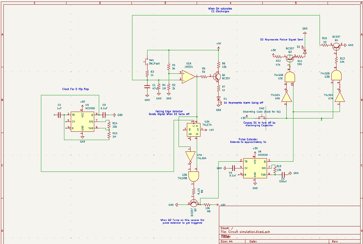
A burglary alarm system that uses LEDs and push buttons to represent an alarm being tripped (SW1), an alarm going off (D1), an alarm being disarmed (SW2), and a police signal being sent (D2).
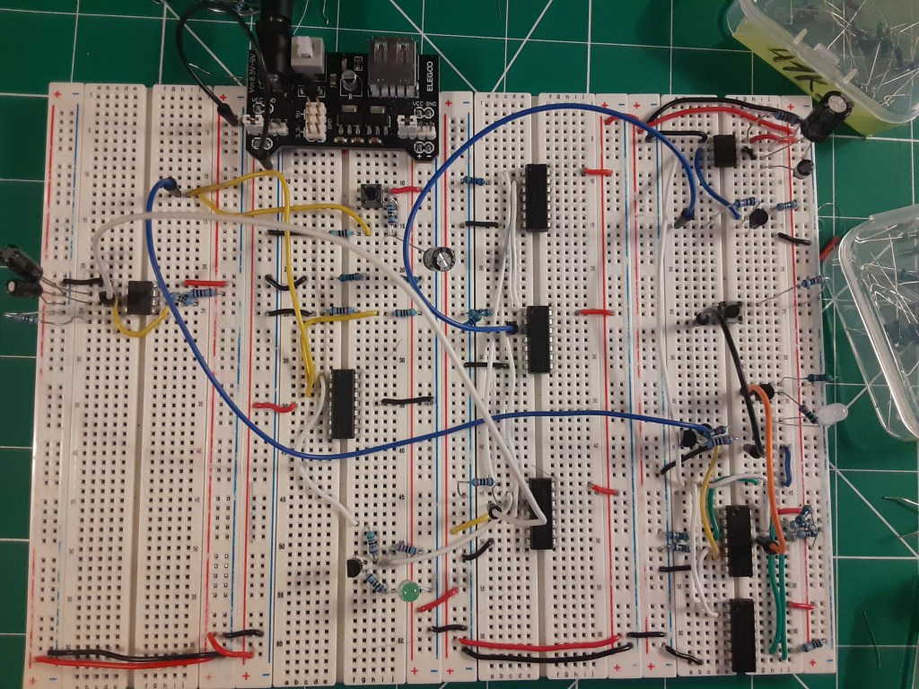
How was this built?
Built using only Hardware. ICs like the NE555 and the 74XXXX series were vital in determining the correct logic.
Transistors ensured LED’s turned on without the influence of noise and to be able to use voltage levels (Base of Q1) to send signals indicating that the alarm going off (D1) was turned off.
Due to the finicky nature of ICs, noise reduction was crucial in the working of the circuit. Decoupling capacitors (C3, look at “Clock for D flip flop”), pull-up and pull-down resistors (for the 74XXXX series) were used to make sure that the signals being detected were the right ones and were not just noise.
Why did I build this?
This was my first-ever project, and I know that as a future engineer, I want to design electronic systems that positively impact people’s lives on a day-to-day basis. Therefore, I decided to create a circuit that can be applied to real-life situations, such as a security system.
I wanted to challenge myself, so I created one rule: Do not use a microcontroller. This led me to gain a strong understanding of electronics principles and circuit design.

Leave a comment